[Get 32+] Basic Electrical Outlet Wiring Diagram
Get Images Library Photos and Pictures. Split Plug Wiring Diagram Home Electrical Wiring Basic Electrical Wiring Electrical Wiring Wiring A Switched Outlet Wiring Diagram Electrical Online Diagram Thermostat Wiring Diagrams 10 Most Common Wiring Diagram Full Version Hd Quality Wiring Diagram Yamaha135 Atelierfrancais Fr Electrical Outlet Wiring Colors Creative Karr Alarm System Antidiler
Black hot wire to a gold colored terminal screw. Any break or malfunction in one outlet will cause all the other outlets to fail.
. Manuals Basic Electrical Wiring Outlet Full Version Hd Quality Wiring Outlet Manualtoguidecom Hardfolk It Electricity 101 Basic House Wiring Diagrams Chart Ducati Ignition Switch Wiring Diagram 2004 Bonek Sampai Malam Warmi Fr
 Basic Electrical Wiring Diagram For Android Apk Download
Basic Electrical Wiring Diagram For Android Apk Download Wire a dryer outlet how to wire a dryer outlet how to wire a 3 prong dryer outlet and a 4 prong dryer outlet.
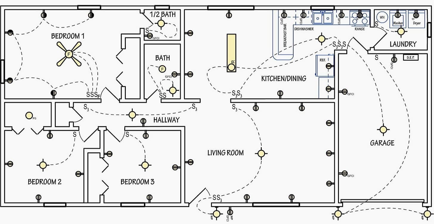
. Electrical outlet boxes can have numerous nm cables going in and out. This is how to rough in electrical wiring yourself. They are connected straight from the power source and are hot at all times.
Connect the new wires to the new outlet. There are two vertical lines. Two wires carrying 120 volts each can be combined to provide high voltage to heating circuits and one of the 120 volt wires can serve lights or other low voltage circuits in the appliance.
To wire multiple outlets follow the circuit diagrams posted in this article. Make sure the cable sheath remains secured inside the box. In this wiring the first and 3rd outlet hot terminals are connected to the line 2 blue and the second and last outlets hot terminals are connected to the line 1 red.
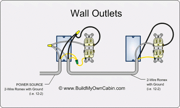
A how to video on wiring an electrical outlet. Multiple outlet in serie wiring diagram. In the diagram below a 2 wire nm cable supplies line voltage from the electrical panel to the first receptacle outlet box.
Ladder diagram are electrical diagrams that represents an electrical circuits in industries to document control logic systems. Bare wire to the green grounding screw. And second its easier to press the outlet back into the box if fewer of its screws are connected to wires.
One of the most common wiring configurations your going to find with outlets are shown in the diagram below. The video covers how to strip electrical wire create loops on the load neutral and ground wire and how to. The 50 amp circuit is required for new installations of some large appliances requiring 240 volts.
Ground wire is connected to the outlets as well as shown in the fig. Wire the new electrical outlet. The red wire switched hot wire going to the outlet wires into the other side of the switch and the white wires neutral tie together to complete the return side of the circuit.
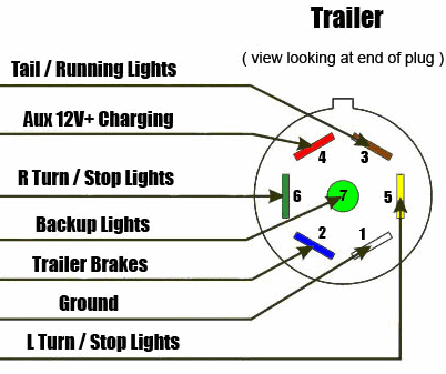
White neutral wire to a silver colored terminal screw. It resemble a ladder which is why it is named ladder diagram. Wire a trailer how to wire a trailer i will show you basic concepts and color codes for a 4 wire 6 wire and 7 wire connector used for wiring trailers.
Instead use wire connectors to connect the neutral hot and ground wires along with 6 in long pigtails then connect the pigtails to the outlet. This repeats until the end of the chain. Diagrams shown on this page are simplified for clarity.
See actual switch box wiring diagram. The neutral is connected from the main breaker to all outlets neutral terminal. Computer connection diagram computer connection diagram how to hook up a computer.
The neutral wire. These outlets are not switched. The left vertical line represents power rail voltage source while the right vertical line represents the ground or neutral.
The black wire line and white neutral connect to the receptacle terminals and another 2 wire nm that travels to the next receptacle. For wiring in series the terminal screws are the means for passing voltage from one receptacle to another. The receptacle should be wired to a dedicated 50 amp circuit breaker using 6 awg cable.
This wiring diagram is used for 50 amp appliance outlet. Wiring a 50 amp 240 volt appliance outlet. Mount the new box in the opening.
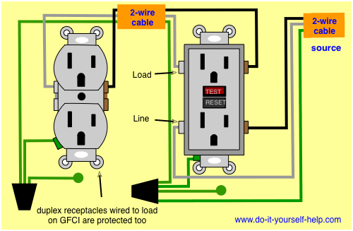 Wiring Diagrams For Electrical Receptacle Outlets Do It Yourself Help Com
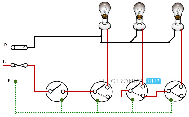 Electrical Wiring Systems And Methods Of Electrical Wiring
Basic House Wiring Diagrams Chart Ducati Ignition Switch Wiring Diagram 2004 Bonek Sampai Malam Warmi Fr
 Diagram 50a Receptacle Wiring Diagram Full Version Hd Quality Wiring Diagram Diagramssild Ilpeocio It
 Guidelines To Basic Electrical Wiring In Your Home And Similar Locations
 Diagram Basic Electrical Wiring Diagrams Range Full Version Hd Quality Diagrams Range G12schematics Jeanpierresauser Fr
 Electrical Gfci Outlet Wiring Diagram Outlet Wiring Gfci Electrical Wiring
 Diagram Basic Electrical Wiring Diagrams Lights Full Version Hd Quality Diagrams Lights Df1x44 Epaviste Gratuit Idf Fr
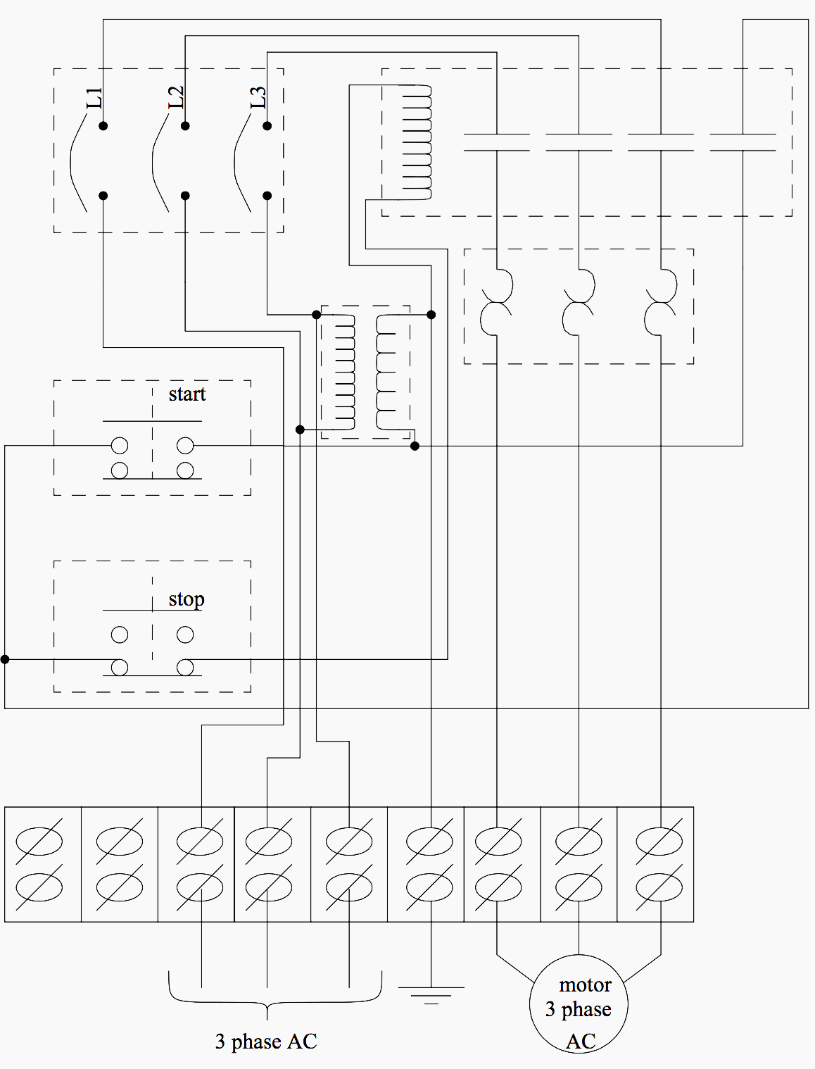 Diagram Belajar Wiring Diagram Panel Full Version Hd Quality Diagram Panel Mcgwiring2a Amoresanoamoremalato It
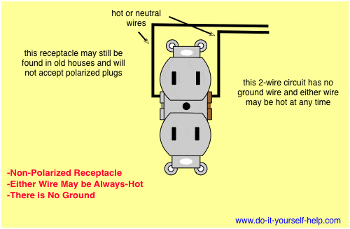 Wiring Diagrams For Electrical Receptacle Outlets Do It Yourself Help Com
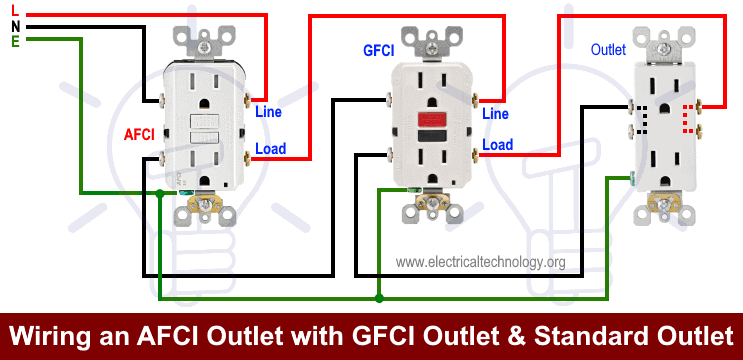 How To Wire An Outlet Receptacle Socket Outlet Wiring Diagrams
Diagram Rv Plug Wire Diagram Full Version Hd Quality Wire Diagram Pvdiagramjacquelinem Bigali Fr
Diagram Directv Basic Wiring Diagram Full Version Hd Quality Wiring Diagram Thendiagram11 Slowlifeumbria It
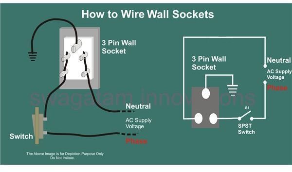 Help For Understanding Simple Home Electrical Wiring Diagrams Bright Hub Engineering
 Diagram Gfci Wiring Multiple Outlets Diagram Full Version Hd Quality Outlets Diagram Furnacewiring9 Indebitoilfilm It
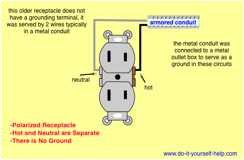 Wiring Diagrams For Electrical Receptacle Outlets Do It Yourself Help Com
 7 Pin Trailer Plug Wiring Diagram For Chevy Wiring Diagram Usage1 Usage1 Concorsomusicalmuseo It
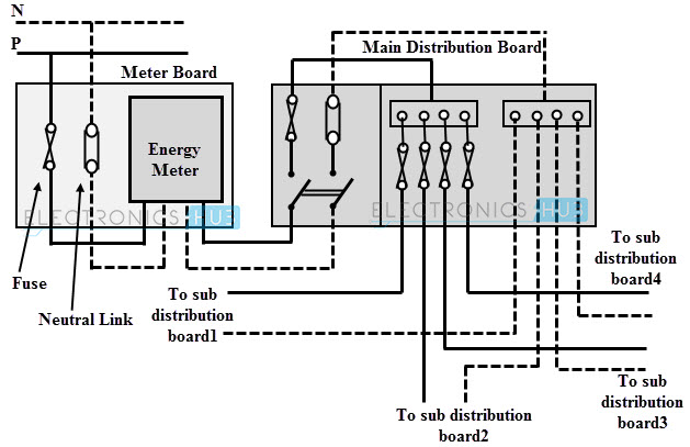 Electrical Wiring Systems And Methods Of Electrical Wiring
 1997 Nissan V6 Spark Plug Wiring Diagram Wiring Diagram Enter 1 Enter 1 Donnaromita It
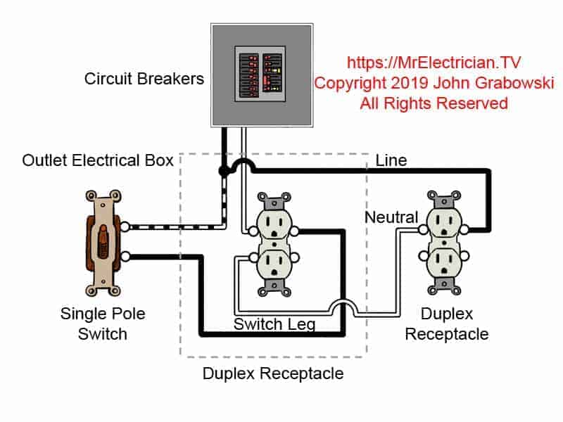 Breaking Tab Wiring Schematic 98 4 3 Engine Diagram Coded 03 Chevyss Genericocialis It
Diagram Basic Wire Diagram Electric Heat Full Version Hd Quality Electric Heat Pischematic11 Ancoraweb It
Komentar
Posting Komentar